Fiber Geometry System FGC Array
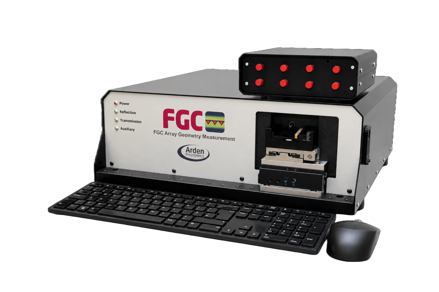
An automated measurement system for the geometry of 1D and 2D Fiber Array Units (FAUs) and MT ferrules, reporting core X-Y positions, core-to-core pitch and PM stress rod angles.
Technical overview
The FGC Array illuminates the core of each fiber in an array and images it through an infinity-corrected objective onto a high-resolution CMOS camera, using a motorised linear stage to scan across the array. Proprietary distortion-correction algorithms and the precision stage give core X and Y position repeatability down to 0.05 um. It accepts arrays up to 22 mm wide and 0.8 mm tall on a tiltable 32 mm mount with -8 to +8 degrees of tilt, covering single-row and multi-row FAUs as well as MT ferrule assemblies referenced to their guide pin holes. Up to six illumination units can be linked to one system to support bare fiber, ribbon, MTP, FC/PC and FC/APC terminated pigtails.
Features
- Core Illumination Technology: the core of each fiber in the array is illuminated to enhance the core-to-core measurement accuracy and repeatability
- Fully Automated Translation Stage: precision linear stage delivers repeatability down to 0.05 um for core X & Y position
- Advanced Fiber Array Unit Mounting: tiltable 32 mm mount and adjustable-width array holder for fiber arrays from 2.5 mm to 22 mm, tilt angles from -8 to +8 degrees
- Enhanced Optical System & Algorithm: infinity-corrected objective and high-resolution CMOS camera with proprietary distortion correction
- Multi-Row 2D Array Measurement up to 22 mm wide and 0.8 mm tall
- Lower latency FGC Array V2.0 Software with customisable measurement templates
- Additional Fiber Core Illuminators including a 32 mm wide FAU illuminator
- Up to six illumination units can be linked to an FGC-Array system
Specifications
| Parameter | Value |
|---|---|
| Array block width (V-groove array) | Up to 22 as standard mm |
| Scan range (V-groove array) | Up to 20 (core to core pitch can be measured within this range) mm |
| End face vertical angle (V-groove array) | -8 to +8 tilt angle degrees |
| Fiber types (V-groove array) | Single or multi row - singlemode, multimode, PM |
| Core pitch (V-groove array) | Any arbitrary sequence, missing/non-illuminated cores are permissible |
| Standard parameters (V-groove array) | X-Y positions of cores, PM stress rod angle (external PM illuminator and compatible FAU holder required) |
| Measurement time (V-groove array) | 30 second setup/analysis, plus 5 seconds per core |
| Reference line (V-groove array) | First to last core, Fiber cladding reference points, Best Fit |
| Guide pin hole OD (MT ferrule) | 0.5 / 0.7 mm |
| Guide pin hole pitch (MT ferrule) | 4.6 / 5.3 mm |
| Measurement range (MT ferrule) | Core position can be measured vertically up to 0.8 mm |
| End face vertical angle (MT ferrule) | -8 to +8 tilt angle degrees |
| Ferrule types (MT ferrule) | Single or multi row - singlemode, multimode |
| Standard parameters (MT ferrule) | X-Y positions of cores |
| Measurement time (MT ferrule) | 30 second setup/analysis, plus 5 seconds per core |
| Reference line (MT ferrule) | First to last core, Guide pin hole reference points, Best Fit |
| Measurement wavelength | 630 nm |
| Polarisation-maintaining fiber support | PANDA style PM only, illuminates fiber arrays up to 9 mm width (not compatible with standard adjustable holder); bow-tie style fibers can be imaged and core centroid determined, but not the angle of the fast/slow axes |
| Stage translation accuracy (1 sigma) | 0.05 um + 0.008 * L (L is the horizontal distance between points in mm); measured on the X-axis translation stage only at a stage temperature of 26 +/- 2 degC |
| Core X & Y positions repeatability (1 sigma) | 0.05 um |
| Repeatability basis | Measured using a 28 fiber array (127 um nominal pitch), when re-inserting the sample |
| Field of view | 1100 (V) x 800 (H) um |
| Weight | 23 kg |
| Size | 0.46 x 0.46 x 0.2 m |
| Operating temperature | 10 - 30 degC |
| Performance specification validated at | 21 +/- 2 degC |
| Power supply | 24 V (external power supply supplied) |
| Power consumption | 120 W |
| Data interface | 1 x USB 3.0 (USB B to USB A: 1 m cable supplied) |
| Computer requirements | All FGC Array systems are supplied with a computer running up-to-date Windows operating system |
| Illuminators | FGA-PMI-630 (630 nm PM), FGA-PMI-455 (455 nm PM), FGA-EXT-FC (8 x FC), FGA-EXT-MTP (6 x MTP/MPO), FGA-EXT-BF (Fujikura style holder, bare fibers and ribbons), FGA-EXT-Array (32 mm wide Arden holders) |
| Holders | FG-H-VA (adjustable width 2.5 - 22 mm), FG-H-VAPM (2.5 to 9 mm, PM illuminator compatible), FG-H-VAMT (MT ferrules, with backlit guide holes) |
| Datasheet document reference | APD0284 V1.0, issued 9 July 2026 |
Applications
- Characterisation of 1D and 2D Fiber Array Units (FAUs)
- Measurement of MT ferrule assemblies
- 2D MPO connector and 2D Fiber Array Unit production for high performance data centres
- R&D, laboratory and production quality control of fiber arrays
You may also like
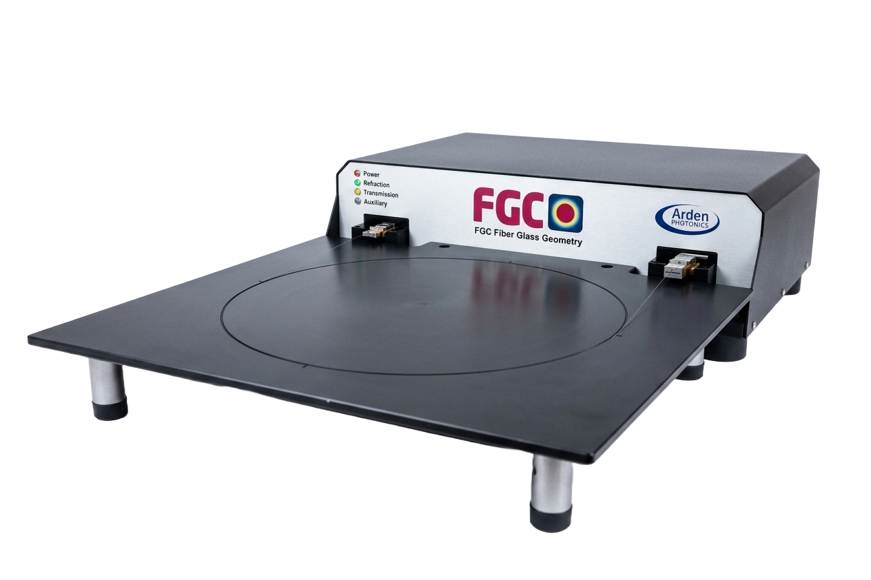
A glass geometry measurement system for specialty fibers with cladding diameters from 80 um to 250 um, aimed at hollow core, multi-core and polarisation-maintaining fiber.
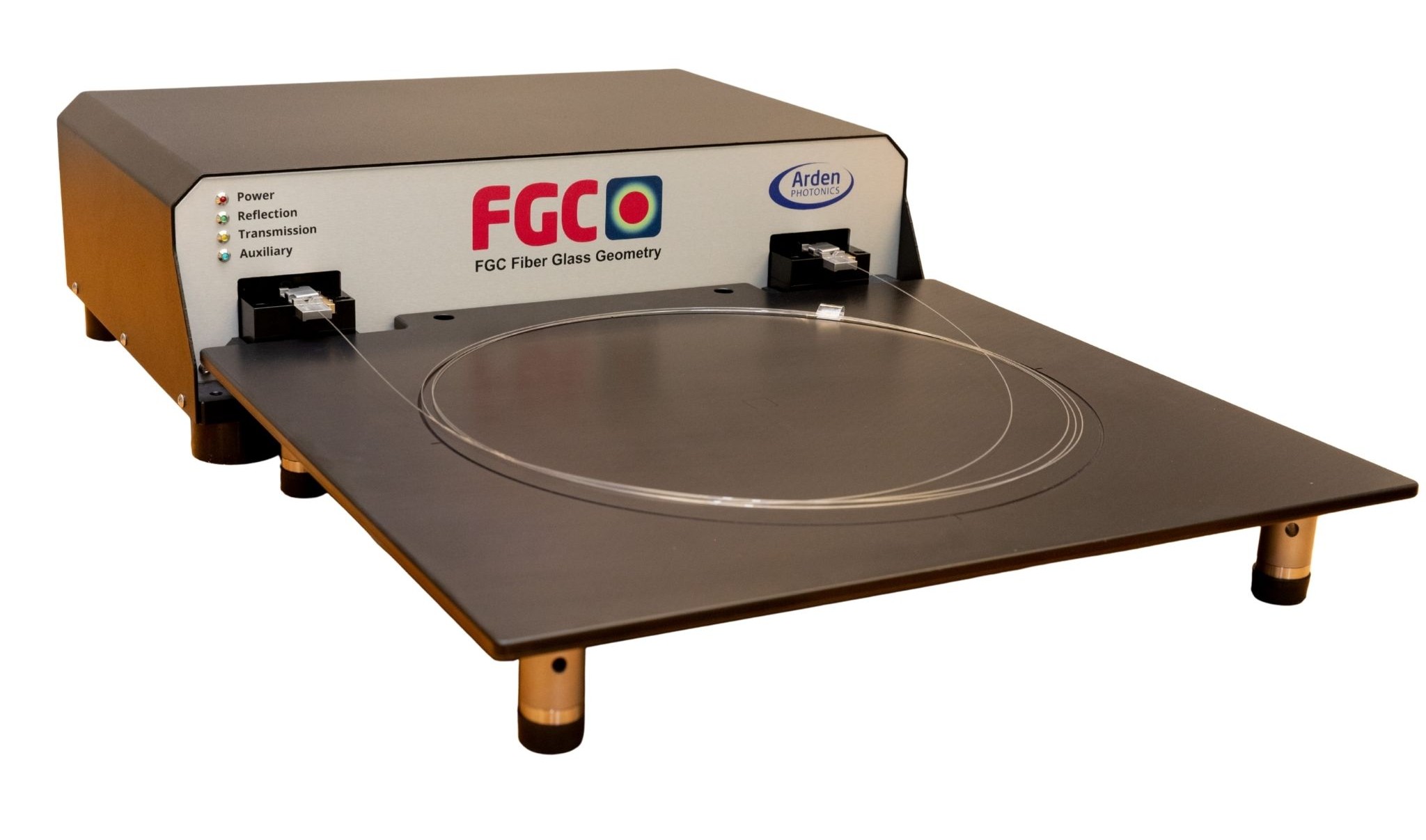
A glass geometry measurement system for standard and specialty fiber up to 800 um in diameter, measuring core and cladding diameter, non-circularity and concentricity in under 10 seconds.
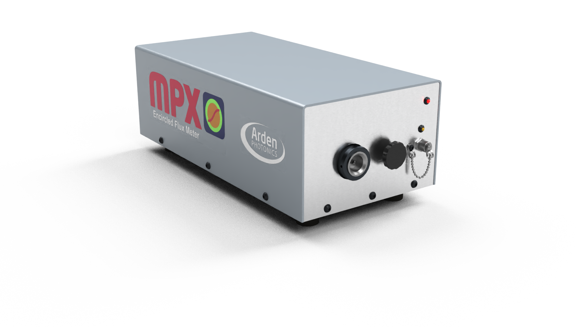
A benchtop instrument that measures the modal launch condition (Encircled Flux) of a multimode light source and patchcord at 850 nm. It is used to verify that a test source meets the launch requirements of the multimode loss-measurement standards.
Need help specifying this?
Our application engineers will confirm specifications with the manufacturer and quote for your configuration.
Request Info